Difference between revisions of "User Guide"
(→Layout) |
|||
| Line 22: | Line 22: | ||
===Wizards=== | ===Wizards=== | ||
| + | [[Image:weavewizard.png]] | ||
| + | |||
The wizards are designed to create textile models with a minimum amount of input. Currently only the weave wizard has been implemented which generates models of 2d and 3d weaves. Plans to include wizards for other fabric types are in progress. | The wizards are designed to create textile models with a minimum amount of input. Currently only the weave wizard has been implemented which generates models of 2d and 3d weaves. Plans to include wizards for other fabric types are in progress. | ||
Revision as of 10:11, 7 September 2007
Graphical User Interface
The GUI is the easiest way to use TexGen, in previous version a lot of TexGen features were not accessible via the graphical user interface. However considerable effort has been made to improve this, notably version 3.1 includes a modelling interface for interactive manipulation of textile geometry and version 3.2 includes a 3d weave wizard. For those comfortable with doing a bit of programming, the Python interface is recommended.
Layout
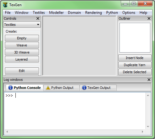
At the centre is a window showing a 3d representation of the textile geometry. Initially when TexGen is loaded this window will be empty, this is because no textile models will have been created yet. After creating a textile model it will become visible, if several textile models are created they will each be open in a separate tab allowing you to work with several models at once.
There are several other windows which can be switched on and off via the drop-down menu at the top in the "Window" section. By default the controls and logs windows will be visible.
The controls window is separated into various sections: Textiles, Modeller, Domain, Rendering and Python. Note that most of these controls are also accessible via the drop-down menu at the top. These controls are used to create textile models, manipulate them and control how they are rendered to the screen amongst other things.
The log windows at the bottom contains an interactive Python Console along with Python Output and TexGen Output windows. The interactive console allows the user to type Python commands and see the results in an interactive manner. This can be useful for small operations and learning how to use the python scripting interface. For inputting a large number of Python commands it is more convenient to save it in a Python script and execute it all at once.
The Python Output log window displays all the Python code executed by the GUI. Essentially every button pressed in the user interface will create a Python command. This is done by design, making it possible to record Python scripts while interacting with the GUI. If you know how to do something with the GUI, you then automatically know how to do it with a Python script because the code is displayed.
The TexGen Output log window displays log and error messages from TexGen. These generally include information on what TexGen is doing, if something goes wrong it is useful to read the log to find out what happened. Error messages will be displayed in red so that they can be easily located.
If new messages are posted one of the log windows while it is inactive, the icon above the window will change. In the case of receiving an error message the icon will change to an error icon.
Finally the outliner window which is hidden by default gives tree representation of the textile model. Which each textile is composed of a several yarns each of which is composed of nodes. This will be covered in more detail in the modelling section.
Wizards
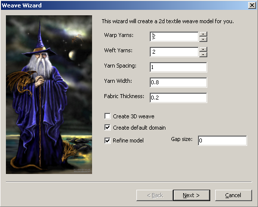
The wizards are designed to create textile models with a minimum amount of input. Currently only the weave wizard has been implemented which generates models of 2d and 3d weaves. Plans to include wizards for other fabric types are in progress.
To use the weave wizard, select Textiles from the controls window and click on the Weave button. Or alternatively select Textiles → Create Weave... from the drop down menu at the top. The user must then fill in the textile data as requested, tool tips for each section can be viewed by holding the mouse over the control for about a second.
After filling in the basic details about the woven fabric, clicking on Next will bring you to the weave pattern user interface.
Modeller
While the wizards provide an easy way to create textile models, flexibility and control over the geometry is sacrificed. On the other end of the spectrum the modeller allows users total control over textile geometry at the expensive of a slightly steeper learning curve.
To invoke the modeller select the modeller tab on the controls section and click on the create textile button. You will be prompted to enter a name for the textile, this can be left blank in which case a default name will automatically be assigned.
Begin by create a single yarn, this is achieved by clicking on the create yarn button. You will be prompted to enter the origin and end coordinates of the yarn along the number of nodes used to represent the yarn. The yarn will always initially be created as a straight line with equispaced nodes.
Once the yarn has been placed it should be visible on screen in wire frame mode. Clicking on the yarn with the left mouse button will enable you to select the yarn at which point it should turn white. Once the yarn is selected you should see the three X, Y and Z axes visible at the centre of the yarn. The yarn can be moved by click and dragging on any of these axes to move it in the corresponding direction. Similarly nodes can be selected and moved in the same manner. The nodes are displayed as spheres on the centreline of the yarn.
An alternative manner to select yarns and nodes is to select them in the outliner. To open the outliner click on Window → Outliner from the drop-down menu at the top. The yarn and its associated nodes should then be visible in the tree control. Clicking on them results in them being selected. Multiple yarns and nodes can be selected at once by holding down Ctrl or Shift while selecting.
Yarns and nodes can also be moved around by typing their coordinates directly in the modeller controls window. This provides a precise way to position nodes and yarns. Precise positioning can also be achieved interactively by enabling snapping and dragging them in the render window.
Additional nodes can be added to the yarn by selecting a node and clicking on Insert node in the outliner. The new node will be inserted in between the selected node and the previous one, this doesn't work if the first node in the yarn is selected. The same can be accomplished in the render window by selecting the node and pressing the Insert key.
Yarns can be duplicated by selecting the yarn and clicking on duplicate in the outliner or pressing d on the keyboard. The duplicated yarn will be an exact copy of the yarn at the same location, after duplicating the yarn should be moved so that they no longer overlap.
Nodes and yarns can be deleted by selecting them and clicking on delete in the outliner or pressing Delete on the keyboard.
Cross-sections can be assigned to yarns by selecting them and click on Assign section button in the modeller control window. Various options are available such as applying a constant cross section or interpolating between sections defined at different positions along the length of the yarn.

