Difference between revisions of "User Guide"
| (172 intermediate revisions by 2 users not shown) | |||
| Line 1: | Line 1: | ||
| − | == | + | ==Introduction== |
| − | + | This user guide gives instructions for using TexGen via the graphical user interface (GUI). A practical introduction to using TexGen with worked examples and exercises can be found in the [https://link.springer.com/chapter/10.1007/978-3-030-91515-5_6 TexGen chapter] in the book Advanced Weaving Technology, DOI https://doi.org/10.1007/978-3-030-91515-5. | |
| + | |||
| + | ==Layout== | ||
| + | [[Image:layout.png]] | ||
| − | |||
At the centre is a window showing a 3d representation of the textile geometry. Initially when TexGen is loaded this window will be empty, this is because no textile models will have been created yet. After creating a textile model it will become visible, if several textile models are created they will each be open in a separate tab allowing you to work with several models at once. | At the centre is a window showing a 3d representation of the textile geometry. Initially when TexGen is loaded this window will be empty, this is because no textile models will have been created yet. After creating a textile model it will become visible, if several textile models are created they will each be open in a separate tab allowing you to work with several models at once. | ||
| Line 19: | Line 21: | ||
Finally the outliner window which is hidden by default gives tree representation of the textile model. Which each textile is composed of a several yarns each of which is composed of nodes. This will be covered in more detail in the modelling section. | Finally the outliner window which is hidden by default gives tree representation of the textile model. Which each textile is composed of a several yarns each of which is composed of nodes. This will be covered in more detail in the modelling section. | ||
| − | === | + | ==Textiles Menu== |
| − | The wizards are | + | |
| + | ===Create Empty Textile=== | ||
| + | This option creates an empty textile ready to have yarns added using the Modeller options. | ||
| + | Either: | ||
| + | # Select Controls -> Textiles -> Empty, or | ||
| + | # Select Main Menu -> Textiles -> Create Empty... | ||
| + | |||
| + | A Textile Name dialog will then be displayed for entering a name for the textile. Leave blank for a default name of Textile, Textile-2 etc. | ||
| + | |||
| + | |||
| + | ===Create Weave=== | ||
| + | |||
| + | [[Image:WeavewizardShear.png]] | ||
| + | |||
| + | To use the weave wizard either: | ||
| + | # Select Controls -> Textiles -> Weave, or | ||
| + | # Select Main Menu -> Textiles -> Create Weave... | ||
| + | |||
| + | ====Create 2D Weave==== | ||
| + | |||
| + | Fill in the textile data on Weave Wizard as follows. Tool tips for each section can be viewed by holding the mouse over the control for about a second. | ||
| + | * Warp Yarns, Weft Yarns - select number of yarns required | ||
| + | * Yarn Spacing - by default this is the same for both warp and weft yarns | ||
| + | * Yarn Width - by default this is the same for both warp and weft yarns | ||
| + | * Fabric Thickness - at this point the yarn height will be taken to be half the fabric thickness (this can be altered in the next dialog if necessary | ||
| + | * Create 3D Weave - leave unchecked for 2D weave | ||
| + | * Create Layered Textile - when checked the Number of Weave Layers control is enabled for selection of the number of layers of the 2D textile. | ||
| + | * Create Default Domain - the default domain is the same as the unit cell, producing a box shaped domain with orthogonal faces. | ||
| + | * Create Sheared Domain - enabled when the Shear textile option is selected. Generates a unit cell domain which lines up with the angle of the sheared yarns in the ''x''-''y'' plane. | ||
| + | * Refine model - if selected this will automatically adjust yarn cross-sections and rotations to create a textile without intersections and with a specified gap between yarns | ||
| + | ** Gap Size - Specify the gap between yarns when Refine Model is selected | ||
| + | * Shear textile - if selected this will generate a textile with the weft yarns sheared at the shear angle specified. | ||
| + | ** Shear angle - Specify the shear angle in degrees when Shear Textile is selected | ||
| + | |||
| + | Select Next to proceed to Weave Pattern dialog: | ||
| + | |||
| + | [[Image:2DWeavePatternDialog.png]] | ||
| + | |||
| + | This window allows the weave pattern to be set and yarn spacing, width, and height to be adjusted. | ||
| + | |||
| + | * Click on yarn cross-over to switch the vertical order of the crossing yarns and thus define the weave pattern. | ||
| + | * Right click on the top-down view to select a cross-section passing through the selected point. This gives a schematic preview of the cross-section. | ||
| + | |||
| + | * Set yarn spacing, width and height | ||
| + | ** Click on boxes running along left and top of window to select one yarn | ||
| + | ** Control or Shift and right click to select multiple yarns | ||
| + | *** Boxes representing selected yarns now appear in red | ||
| + | *** Right click to give pop-up menu. Select required option and enter value in subsequent dialog box | ||
| + | *** Changes to width and height will be applied to all selected yarns. Changes to yarn spacing will modifies the spacing between the selected yarn and the yarn after it. | ||
| + | |||
| + | ====Create 3D Weave==== | ||
| + | |||
| + | * Create 3D Weave - check this box | ||
| + | * Refine Model/Gap size - these options will now be greyed | ||
| + | * Fill in the rest of the textile data on the Weave Wizard as described for a 2D weave above | ||
| + | |||
| + | Select Next to proceed to Weave Pattern dialog: | ||
| + | |||
| + | [[Image:weavepattern.png]] | ||
| + | |||
| + | This window allows the weave pattern to be set and yarn spacing, width, and height to be adjusted. Layers of warp and weft yarns can also be added and removed. | ||
| + | |||
| + | * Click on the top-down view to select a cross-section passing through the selected point. This gives a schematic preview of the cross-section. | ||
| + | ** The cross-section view is very important when creating 3d weaves because it is the only way to set the vertical order of the warp and weft yarns. Click and drag a cross-over up or down to move it to the desired location. By doing this for each cross-section one after the other the weave pattern can be completely defined. | ||
| + | |||
| + | * Add/remove layers | ||
| + | ** Click on boxes running along left and top of window to select one yarn | ||
| + | ** Control or Shift and Click to select multiple yarns | ||
| + | *** Boxes representing selected yarns now appear in red | ||
| + | *** Right click to give pop-up menu. | ||
| + | *** Select Add Layers/Remove Layers to add/remove one yarn to each set of yarns chosen | ||
| + | * Set yarn spacing, width and height as for 2D Weave described above | ||
| + | |||
| + | ===Create 3D Weave=== | ||
| + | |||
| + | To use the 3D weave wizard either: | ||
| + | # Select Controls -> Textiles -> 3D Weave, or | ||
| + | # Select Main Menu -> Textiles -> Create 3D Weave... | ||
| + | |||
| + | First select the weave type to be created and then select Next to continue to the next page. | ||
| + | |||
| + | [[Image:3DWizardPage1.png]] | ||
| + | |||
| + | |||
| + | Input the data for the weft yarns on the 3D Weave Wizard as follows. Tool tips for each section can be viewed by holding the mouse over the control for about a second. | ||
| + | |||
| + | [[Image:3DWizardWeftPage.png]] | ||
| + | |||
| + | * Yarns - select number of yarns required | ||
| + | * Number of Yarn Layers - select the number of weft yarn layers | ||
| + | ** Note that for angle interlock weaves the number of yarns and layers are tied so that the correct weave pattern is achieved. Changing one will cause the other to be changed automatically if necessary. | ||
| + | * Yarn Spacing - this is the spacing allowed for the yarn, the yarn being positioned centrally within the space assigned. | ||
| + | * Yarn Width - specify the yarn width | ||
| + | * Yarn Height - specify the yarn height | ||
| + | * Power Ellipse Section Power - specify power. The resulting shape is shown on the dialog | ||
| + | * Offset weft yarns - this is only enabled for the angle interlock weave and results in a weave pattern where rows of weft yarns are offset by half a yarn spacing | ||
| + | |||
| + | |||
| + | Select Next to proceed to warp yarn input dialog. Enter data as for the weft yarns. | ||
| + | [[Image:3DWizardWarpPage.png]] | ||
| + | *Total number of yarns in warp direction: This is the total of both straight warp yarns and through thickness binder yarns. | ||
| + | * Ratio of Binder Yarns to Warp Yarns: Specifies the order of binder/warp yarns. If the warp ratio is 0 then all yarns in the warp direction are binder yarns. | ||
| + | * For angle interlock and layer-to-layer weaves the number of layers input is disable and is assigned automatically depending on the number of weft layers. | ||
| + | |||
| + | |||
| + | Select Next to proceed to the binder yarn input dialog. | ||
| + | |||
| + | [[Image:3DWizardBinderPage.png]] | ||
| + | * Yarn Width - specify the yarn width | ||
| + | * Yarn Height - specify the yarn height | ||
| + | * Yarn Spacing - specify the yarn spacing | ||
| + | * Gap size - where possible this forces a gap of the given size between yarns | ||
| + | * Power Ellipse Section Power - specify power. The resulting shape is shown on the dialog | ||
| + | * Number of Binder Yarn Layers - this is only enabled for layer-to-layer weaves | ||
| + | * Refine - this option is only available for orthogonal weaves. Check the box to refine the textile. | ||
| + | ** Target thickness - only enabled if refine is selected. Specify the required target thickness for the refined textile. Defaults to the undeformed thickness given by the warp and weft yarn startin heights. | ||
| + | |||
| + | |||
| + | Select Next to proceed to the Weave Pattern dialog or to the Yarn Properties dialogs if the Refine option is selected. | ||
| + | |||
| + | [[Image:3dWizardWeaveControl.png]] | ||
| + | |||
| + | This window allows the weave pattern to be set and yarn spacing, width, and height to be adjusted. | ||
| + | |||
| + | Binder yarns are green, warp yarns blue. | ||
| + | * Orthogonal weave - click on binder yarn crossover point on top view to toggle the binder yarn between top and bottom of the weave. | ||
| + | * Angle interlock - click on binder yarn crossover point on top view to assign top point of binder yarn pattern. | ||
| + | * Layer-to-layer | ||
| + | ** Click on binder yarn on top view to select. A schematic preview of the side view for this binder position will be displayed below the top view. | ||
| + | ** Drag the binder yarns in the side view to the vertical position required. If there is more than one layer of binder yarns these will all be moved together. | ||
| + | |||
| + | * Set yarn spacing, width and height | ||
| + | ** Click on boxes running along left and top of window to select one yarn | ||
| + | ** Control or Shift and right click to select multiple yarns | ||
| + | *** Boxes representing selected yarns now appear in red | ||
| + | *** Right click to give pop-up menu. Select required option and enter value in subsequent dialog box | ||
| + | *** Changes will be applied to all selected yarns. | ||
| + | |||
| + | |||
| + | [[Image:3DWizardYarnProperties.png]] | ||
| + | |||
| + | A separate dialog will be displayed for warp, weft and binder yarn properties. When refining the textile the yarn volume fractions are calculated to check that, as the yarns are compressed, the volume fractions stay within realistic limits. If these are exceeded then the refine will stop with an error message stating that the target thickness cannot be achieved. | ||
| + | |||
| + | Note that it is not necessary to complete all of these values: either the fibre area, or fibres per yarn and fibre diameter, or yarn linear density and fibre density will be sufficient. | ||
| + | |||
| + | ===Create Layered=== | ||
| + | Either: | ||
| + | # Select Controls -> Textiles -> Layered, or | ||
| + | # Select Main Menu -> Textiles -> Create Layered... | ||
| + | |||
| + | [[Image:SelectLayersDialog.png|500px]] | ||
| + | |||
| + | The Select Textile Layers dialog will be displayed. On the left hand side this lists all of the textiles currently loaded in the GUI. These can be selected and then the Add Layer button used to add them to the Layers window on the right hand side. The textiles listed in the Layers window can then be selected and the Remove Layer, Move Layer Up and Move Layer Down buttons used to select the order required. The layered textile will be created with the textiles in the order shown in the dialog as shown below. | ||
| + | |||
| + | [[Image:4LayeredTextile.png|500px]] | ||
| + | |||
| + | ===Set Layer Offsets=== | ||
| + | [[Image:Layer Offsets Dialog.png|right]] | ||
| + | Select Main Menu -> Textiles -> Set Layer Offsets | ||
| + | |||
| + | The Layer Offsets dialog will be displayed. | ||
| + | * Constant - enter an x and y offset. This offset will be applied from the bottom of the stack to each layer, relative to the one below. | ||
| + | * Random - random offsets are allocated and are displayed in the table on the dialog. | ||
| + | * Edit Offsets - the table can be edited and the offsets entered. | ||
| + | [[Image:4LayeredOffset.png|400px]] | ||
| + | |||
| + | ===Nest Layers=== | ||
| + | Two nesting options are available, either maintaining the layer offsets already set or moving the layers relative to each other in order to achieve the maximum nesting. | ||
| + | |||
| + | * Maintaining offset | ||
| + | **Select Main Menu -> Textiles -> Nest Layers -> Keep Offsets | ||
| + | **The layers will be moved together, in the z direction, as much as possible without causing intersections. The current x,y offsets between layers is maintained. | ||
| + | |||
| + | * Maximum nesting | ||
| + | **Select Main Menu -> Textiles -> Nest Layers -> Maximum nesting | ||
| + | **The layers will be moved together adjusting the x and y offset between the layers in order to achieve the maximum z movement without causing intersections. | ||
| + | |||
| + | [[Image:4LayeredNested.png|400px]] | ||
| + | |||
| + | ===Edit Textile=== | ||
| + | |||
| + | Either | ||
| + | * Select Textiles -> Edit Textile.. | ||
| + | or | ||
| + | * Select Edit from the Textiles menu in the Controls window | ||
| + | |||
| + | If the textile has been created using one of the wizards then it will be reloaded into the appropriate wizard and the pages can then be edited and the textile regenerated. | ||
| + | |||
| + | Note: If the textile has been edited (eg. nodes have been moved) this will not be reflected in the regenerated textile. | ||
| + | |||
| + | ===Rotate Textile=== | ||
| + | [[Image:RotateTextileDialog.png|right]] | ||
| + | Either | ||
| + | * Select Textiles -> Rotate Textile | ||
| + | or | ||
| + | * Select Rotate from the Textiles menu in the Controls window | ||
| + | |||
| + | The Rotate Textile dialog will be displayed | ||
| + | * Rotation Axis - select the axis of rotation. For in plane rotation select the z-axis | ||
| + | * Angle - rotation angle in degrees | ||
| + | * Rotate Domain - Check to rotate the domain with the yarns. This will result in the section of yarns contained in the domain remaining unchanged (left below). If unchecked the domain will be unchanged and just the yarns rotated (right below). | ||
| + | |||
| + | [[Image:RotateTextileAndDomain.png|400px]] [[Image:RotateTextile.png|400px]] | ||
| + | |||
| + | |||
| + | ==File Menu== | ||
| + | ===Import=== | ||
| + | ====Weave Pattern File==== | ||
| + | This option generates a TexGen model from a weave pattern file in the format specified below. | ||
| + | *Select File->Import->Weave Pattern File... | ||
| + | *The Open Weave Pattern File dialog is displayed, from which a file for import may be selected. | ||
| + | ** Weave Pattern File Format | ||
| + | 2D Satin Weave: | ||
| + | |||
| + | 1 1 1 1 ''First line is layer data, space delimited'' | ||
| + | 1000 ''Weave pattern: 1 = warp lifted'' | ||
| + | 0010 ''0 = warp lowered'' | ||
| + | 0100 | ||
| + | 0001 ''No spacing between entries'' | ||
| + | |||
| + | WEFT_REPEAT ''Use this keyword to generate pattern repeat'' | ||
| + | WIDTH 6 mm ''Yarn data. Row order is unimportant'' | ||
| + | TOW_AREA 0.2 mm^2 ''Width, tow area and weft density must all be'' | ||
| + | WEFT_DENSITY 8 /cm ''specified otherwise default values will be used'' | ||
| + | ''to generate the TexGen model'' | ||
| + | |||
| + | * Additional yarn data. This is optional and will be saved in the yarn properties in the TexGen model | ||
| + | LINEAR_DENSITY 800 tex | ||
| + | FIBRE_DIAMETER 7 um | ||
| + | FIBRE_DENSITY 1.8 g/cm^3 | ||
| + | FIBRE_COUNT 12000 | ||
| + | |||
| + | If the tow area is specified with no tow width and height then the TexGen model is generated using the tow area to calculate the width and height of the yarns, assuming a width to height ratio of 6:1 and an elliptical cross-section. Warp and weft spacings are calculated using the width and weft density information. The data above will generate the model shown below: | ||
| + | |||
| + | [[file:SatinFromWeavePattern.png|400px]] | ||
| + | |||
| + | If the tow area and one of tow width or height are specified then the other dimension (height or width) will be calculated using this data (as in the 3D weave model below). If both tow width and height are specified then these are used, irrespective of the tow area specified. | ||
| + | |||
| + | 3D Weave: | ||
| + | The following file will generate the model shown below: | ||
| + | 1 2 3 4 1 2 3 4 1 2 3 4 1 2 3 4 1 2 3 4 ''Warp layer data, numbered from bottom. Single '1' gives binder yarn'' | ||
| + | 11001111110000001100 | ||
| + | 00001100111111000000 | ||
| + | 10001100100011001000 | ||
| + | 11001000110010001111 | ||
| + | 11110000100000001000 | ||
| + | 00001000000011110000 | ||
| + | WIDTH 7.5 mm | ||
| + | TOW_AREA 0.2 mm^2 | ||
| + | TOW_HEIGHT 0.4 mm | ||
| + | WEFT_DENSITY 8 /cm | ||
| + | FIBRE_COUNT 6000 | ||
| + | LINEAR_DENSITY 800 tex | ||
| + | FIBRE_DIAMETER 6 um | ||
| + | FIBRE_DENSITY 1.8 g/cm^3 | ||
| + | WEFT_REPEAT | ||
| + | |||
| + | [[file:3DWeaveFromPattern.png|400px]] [[file:3DWeaveFromPattern2.png|400px]] | ||
| + | |||
| + | 3D Orthogonal Weave: | ||
| + | 1 1 2 3 4 1 1 2 3 4 ''Warp layer data, numbered from bottom. Single '1' gives binder yarn'' | ||
| + | 1000000000 | ||
| + | 1100001000 | ||
| + | 1110001100 | ||
| + | 1111001110 | ||
| + | 1111101111 | ||
| + | 0000010000 | ||
| + | 0100011000 | ||
| + | 0110011100 | ||
| + | 0111011110 | ||
| + | 0111111111 | ||
| + | |||
| + | ORTHOGONAL ''Use orthogonal keyword to automatically stack weft insertions'' | ||
| + | |||
| + | [[file:OrthogonalFromWeavePattern.png|400px]] | ||
| + | |||
| + | ===Export=== | ||
| + | ====Surface Mesh==== | ||
| + | This option creates a surface mesh corresponding to the mesh shown when using the Rendering -> X-Ray option. | ||
| + | |||
| + | =====VTU and STL File===== | ||
| + | [[file:SurfaceVTUDialog.png|right]] | ||
| + | *Select File->Export->Surface Mesh->STL, VTU File... | ||
| + | *The Surface Mesh Options dialog will be displayed | ||
| + | **Export Yarns: Select to create a mesh of the yarn surfaces | ||
| + | **Trim Surface to Domain: Select to create yarn meshes conforming to domain bounds | ||
| + | **Export Domain: Select to create a triangulated mesh of the domain surfaces | ||
| + | ***Mesh Yarn Ends: Select to create a triangulated mesh across the yarn ends | ||
| + | ***Seed size: Used to adjust size of triangulation | ||
| + | *The Save Mesh file menu will be displayed | ||
| + | **Save as type: Use the drop-down menu to select the file type - VTU, STL (ASCII or binary, or SciRun format | ||
| + | |||
| + | |||
| + | |||
| + | =====ABAQUS File===== | ||
| + | [[file:SurfaceAbaqusDialog.png|right]] | ||
| + | This option will export the surface mesh of the yarns only | ||
| + | *Select File->Export->Surface Mesh->ABAQUS File... | ||
| + | *The ABAQUS Surface Mesh Options dialog will be displayed | ||
| + | **Trim Surface to Domain: Select to output mesh of the yarns bounded by the domain, otherwise the yarns will be output as specified, without repeats | ||
| + | **Contact Surfaces: Outputs element sets for the contact surfaces, either for the upper and lower surfaces separately, or for the whole yarn. Choose Whole Yarn where surfaces are not clearly defined, for example in knitted textiles | ||
| + | |||
| + | |||
| + | |||
| + | ====Volume Mesh==== | ||
| + | [[file:VolumeMeshDialog.png|right]] | ||
| + | This option creates a tetrahedral mesh of both the yarns and matrix (ie of the whole domain). Please note that this algorithm does not work well with textiles with vertical or near-vertical yarns. | ||
| + | *Select File->Export->Volume Mesh | ||
| + | *The Volume Mesh Options dialog will be displayed | ||
| + | **Element Order: Linear creates 4 noded tetrahedra, Quadratic creates 10 noded tetrahedra | ||
| + | **Periodic Meshing: Select to create matching elements on opposite boundaries | ||
| + | **Periodic Boundary Conditions | ||
| + | ***Material Continuum: Assumes a material continuum where the RVE is considered to be infinitely small compared to the size of the engineering part. | ||
| + | ***Single Layer RVE: Gives a 2.5D simulation, assuming a one layer RVE solving in the x and y directions | ||
| + | ***Staggered (Reduced Domain): Applies an offset to the x axis dimension in order to reduce the unit cell size | ||
| + | ****X Offset: Enabled when Staggered PBC is selected. Input the proportion of the x axis dimension by which the domain is offset when applying periodic boundary conditions. | ||
| + | ***Sheared Domain: Only select if 2D sheared textile has been created. Creates tetrahedra which conform to the sheared domain and creates corresponding periodic boundary conditions. | ||
| + | ***None: No boundary conditions are output. | ||
| + | **Periodic boundary condition equations are generated based on the paper "Unit cells for micromechanical analyses of particle-refined composites", Shuguang Li, Anchana Wongsto, Mechanics of Materials 36(2004) 543-572 | ||
| + | **Seed size: Controls the mesh density and corresponds to the approximates edge length of the elements. The default value is 1/20th of the domain diagonal length. | ||
| + | **Merge Tolerance:Any gaps between yarns that are smaller than this tolerance will be merged together. This can help to reduce the number of bad quality elements. | ||
| + | |||
| + | After the Volume Mesh Options dialog is accepted the Save Mesh File dialog will be dispayed. The default type for output is an ABAQUS .inp file. This will create the requested boundary conditions and also associated .ele and .ori files containing yarn orientation and volume fraction information. | ||
| + | Alternatively a VTK unstructured grid file (.vtu) can be selected which will just output the mesh. | ||
| + | |||
| + | ====Tetgen Mesh==== | ||
| + | [[file:TetgenOptions.png|right]] | ||
| + | This option allows export of a tetrahedral mesh generated by Tetgen software. The output file is in Abaqus .inp format. Files with the selected name with .poly and .ele formats are also produced. | ||
| + | :*The Parameters option allows specification of input switches as described here: http://wias-berlin.de/software/tetgen/switches.html. If the Y parameter is used then the function will generate meshes with matching elements on opposite sides of the domain. Use the o2 parameter to generate second order elements. | ||
| + | :*The Seed Size option gives a nominal size for the length of sides of triangles along the domain edge, given as input to the tetgen tetrahedralize function. | ||
| + | :*The Periodic check box should be unchecked for non-periodic textiles. In this case the the domain faces will not be triangulated prior to calling the Tetgen tetrahedralization. | ||
| + | :*The Set Resolution check box allows the textile resolution to be changed. This sets the resolution for the surface mesh which is used as input for the Tetgen meshing | ||
| + | |||
| + | Information on Tetgen software can be found here: http://wias-berlin.de/software/tetgen/. It should be noted that the mesh generation does not always succeed. Most of the time it exits gracefully with a message that tetrahedralization has failed. Sometimes it will cause TexGen to shut down. ''It is strongly recommended that the textile is saved before using this option.'' It has been found that meshes are generated most successfully if a gap is specified in the weave wizards (or if a gap is provided in manually generated textiles). | ||
| + | |||
| + | The .poly file is the input file to the Tetgen tetrahedralize function. A viewer, TetView, can be downloaded here: http://wias-berlin.de/software/tetgen/tetview.html. If the tetrahedralization fails then more information can be gained by downloading the TetGen software and running it from the command line using the .poly file as input. This may show where the program has failed and will enable a bug report to be submitted to the Tetgen project. | ||
| + | |||
| + | ====Voxel Mesh==== | ||
| + | |||
| + | Textiles can be exported in voxel mesh format, either as an ABAQUS file including periodic boundary conditions or at a VTU file containing just the nodes and elements. | ||
| + | |||
| + | =====ABAQUS Voxel File===== | ||
| + | [[file:AbaqusVoxelDialog.png|300px|right]] | ||
| + | *Select File -> Export -> Voxel Mesh -> ABAQUS Voxel File | ||
| + | *The Abaqus Voxel Options dialog will be displayed | ||
| + | **Select the number of voxels required in x,y and z directions | ||
| + | **Select whether to output yarns, matrix or both | ||
| + | **Select whether to use octree refinement and/or smoothing on the voxel mesh. The Octree Refinement dialog will be displayed when OK is selected. | ||
| + | **Element Type: Select either C3D8R or C3D8 | ||
| + | **Periodic Boundary Conditions | ||
| + | ***Material Continuum: Assumes a material continuum where the RVE is considered to be infinitely small compared to the size of the engineering part. | ||
| + | ***Single Layer RVE: Gives a 2.5D simulation, assuming a one layer RVE solving in the x and y directions | ||
| + | ***Staggered (Reduced Domain): Applies an offset to the x axis dimension in order to reduce the unit cell size | ||
| + | ****X Offset: Enabled when Staggered PBC is selected. Input the proportion of the x axis dimension by which the domain is offset when applying periodic boundary conditions. | ||
| + | ***Sheared Domain: Only select if 2D sheared textile has been created. Creates parallelepiped shaped voxels which conform to the sheared domain and creates corresponding periodic boundary conditions. | ||
| + | ***Rotated Domain: Select when a textile has been rotated using the Rotate Textile option with the Rotate Domain option selected. A voxel mesh will be generated which conforms to the rotated domain and creates corresponding periodic boundary conditions. | ||
| + | ***None: No boundary conditions are output. | ||
| + | **Periodic boundary condition equations are generated based on the paper "Unit cells for micromechanical analyses of particle-refined composites", Shuguang Li, Anchana Wongsto, Mechanics of Materials 36(2004) 543-572 | ||
| + | |||
| + | =====Octree Refinement===== | ||
| + | [[file:OctreeRefinementDialog.png|300px|right]] | ||
| + | *Output Surfaces - generate sets of nodes for surfaces between yarns and matrix | ||
| + | *Output cohesive elements – define cohesive contact between yarns and matrix | ||
| + | **Only available if surfaces are output. Nodes on the surfaces between yarns and matrix will be duplicated to "decouple" the yarns and matrix. Cohesive contacts will be created | ||
| + | *Refinement level - Each level of refinement reduces the size of element by the factor of 2. Only elements on the interface between two materials or close to it will be refined to this level of refinement. | ||
| + | ======Smoothing Options====== | ||
| + | The smoothing algorithm will move the yarn surface nodes according to the [http://www.cs.jhu.edu/~misha/Fall07/Papers/Taubin00.pdf Laplacian smoothing algorithm] | ||
| + | *Smoothing | ||
| + | **None - no smoothing applied | ||
| + | **Laplacian - Apply Laplacian smoothing to nodes belonging to yarn-matrix surfaces. Each node will be moved by C1*sum(x_i) where x_i are coordinates of neighbouring nodes | ||
| + | **Non-shrinking - Apply two Laplacian smoothings consecutively with coefficients C1 and C1, where C1 < abs(-C2) | ||
| + | *Iterations - number of smoothing iterations | ||
| + | *Coefficient 1 – [https://diglib.eg.org/handle/10.2312/egst20001029 smoothing coefficient 1] | ||
| + | *Coefficient 2 – [https://diglib.eg.org/handle/10.2312/egst20001029 smoothing coefficient 2] | ||
| + | |||
| + | =====VTU Voxel File===== | ||
| + | [[file:VoxelVTUDialog.png|right]] | ||
| + | *Select File -> Export -> Voxel Mesh -> VTU Voxel File | ||
| + | *The VTU Voxel Options dialog will be displayed | ||
| + | **Select the number of voxels required in x,y and z directions | ||
| + | **Domain Type | ||
| + | ***Box Domain: Default domain created by weave wizards consisting of 6 orthogonal planes | ||
| + | ***Sheared Domain: Only select if 2D sheared textile has been created. Creates parallelepiped shaped voxels which conform to the sheared domain | ||
| + | ***Rotated Domain: Select when a textile has been rotated using the Rotate Textile option with the Rotate Domain option selected. A voxel mesh will be generated which conforms to the rotated domain | ||
| + | |||
| + | |||
| + | |||
| + | |||
| + | |||
| + | |||
| + | |||
| + | ====ABAQUS Dry Fibre File==== | ||
| + | [[file:DryFibreDialog.png|right]] | ||
| + | |||
| + | This will create a mesh of just the yarns in the same form as shown by the Rendering->Render Textile Volume option. | ||
| + | *Select File -> Export -> ABAQUS File -> ABAQUS Dry Fibre File.. | ||
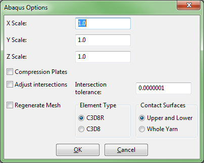
| + | *The Abaqus Options dialog will be displayed | ||
| + | **X, Y and Z Scale:From the scales entered displacements are calculated and applied to the centre node of each yarn, effectively providing the loading for the Abaqus simulation | ||
| + | **Checking the Compression Plates box will add a pair of plates at the top and bottom surface of the domain. | ||
| + | **Adjust intersections: Small, local adjustments to the volume mesh will be made until the intersections are within the selected intersection tolerance. If the intersection is deeper than one volume mesh element then an error message will be displayed and no correction will take place. | ||
| + | **Regenerate Mesh: This will create a new textile based on the adjusted mesh. The volume mesh is regenerated and used to produce the ABAQUS .inp file. This option will create more evenly spaced elements than if the Adjust Intersections option is used on its own. NB. Ensure that the textile is saved before using this option as it will replace the existing textile. | ||
| + | **Element Type: Select either C3D8R or C3D8 | ||
| + | **Contact Surfaces: This option allows contact surfaces to be generated for either the whole yarns or for the upper and lower surfaces. For woven textiles select Upper and Lower. For textiles where there is not a clearly defined upper and lower surface, eg knitted fabric, choose Whole Yarn | ||
| + | |||
| + | ==Modeller== | ||
| + | While the wizards provide an easy way to create textile models, flexibility and control over the geometry is sacrificed. On the other end of the spectrum the modeller allows users total control over textile geometry at the expensive of a slightly steeper learning curve. Note that the modeller can be used to modify models created with the wizards, however if this is done any subsequent changes in the wizard will erase any modifications made. | ||
| + | |||
| + | ===Create Textile=== | ||
| + | To invoke the modeller either: | ||
| + | # Select Controls -> Textile -> Empty, or | ||
| + | # Select Main Menu -> Textiles -> Create Empty... | ||
| + | |||
| + | In both cases a dialog box will be given in order to enter a name for the textile, this can be left blank in which case a default name will automatically be assigned. | ||
| + | |||
| + | ===Add Yarns=== | ||
| + | |||
| + | To add a single yarn either: | ||
| + | # Select Controls -> Modeller -> Yarn, or | ||
| + | # Select Main Menu -> Modeller -> Create Yarn... | ||
| + | |||
| + | In the Create Yarn dialog: | ||
| + | * Enter start and end coordinates for the yarn | ||
| + | * Enter number of nodes | ||
| + | ** The yarn will always initially be created as a straight line with equispaced nodes. | ||
| + | ** Once the yarn has been placed it will be visible on screen in wire frame mode. | ||
| + | |||
| + | ====Edit Yarn/Node Position==== | ||
| + | |||
| + | Select yarn/node using one of the following methods: | ||
| + | # Click on the yarn/node with the left mouse button | ||
| + | # Hold Shift while selecting yarn/node to select multiple yarns | ||
| + | # Click on the yarn/node in the Outliner tree control | ||
| + | # Hold Shift or Ctrl while clicking on yarns/nodes in outliner tree to select multiple yarns | ||
| + | |||
| + | Nodes are displayed as spheres on the centreline of the yarns. | ||
| + | |||
| + | When either yarn or nodes have been selected they will turn white. X, Y and Z axes will be displayed. | ||
| + | |||
| + | To move yarn/node once it has been selected either: | ||
| + | * Click and drag one of the axes displayed. The yarn/node will be moved in the corresponding direction. | ||
| + | ** Precise positioning can be achieved by enabling snapping using Controls -> Modeller -> Snapping | ||
| + | * Edit the coordinates in the Controls -> Modeller -> Position boxes. | ||
| + | |||
| + | ====Add Nodes==== | ||
| + | |||
| + | # Select node | ||
| + | # Click Outliner -> Insert Node, or | ||
| + | # Press the '''Insert''' key | ||
| + | |||
| + | The new node will be inserted in between the selected node and the previous one. Nodes cannot be inserted before the first node in the yarn. | ||
| + | |||
| + | ====Duplicate Yarns==== | ||
| + | |||
| + | # Select yarn | ||
| + | # Click Outliner -> Duplicate Yarn, or | ||
| + | # Press the '''d''' on the keyboard | ||
| + | |||
| + | The duplicated yarn will be an exact copy of the yarn at the same location. After duplicating the new yarn should be moved so that they no longer overlap. | ||
| + | |||
| + | ====Delete Yarns/Nodes==== | ||
| + | |||
| + | # Select yarn | ||
| + | # Click Outliner -> Delete Selected, or | ||
| + | # Press the '''Delete''' key | ||
| + | |||
| + | |||
| + | ===Set Yarn Path Interpolation=== | ||
| + | |||
| + | This specifies how the yarn path is interpolated between the nodes. | ||
| + | |||
| + | # Select yarn | ||
| + | # Select Main Menu -> Modeller -> Assign Interpolation... , or | ||
| + | # Select Controls -> Modeller -> Interpolation | ||
| + | # Select interpolation type from drop-down menu | ||
| + | # Periodic - check to give continuity across yarn repeats as follows: | ||
| + | ## Linear - continuity of cross-section | ||
| + | ## Bezier - continuity of cross-section and tangent(first order continuity) | ||
| + | ## Natural Cubic - continuity of cross-section and both first and second order continuity | ||
| + | |||
| + | |||
| + | ===Set Yarn Cross-Sections=== | ||
| + | |||
| + | # Select yarn | ||
| + | # Select Main Menu -> Modeller -> Assign Section... , or | ||
| + | # Select Controls -> Modeller -> Section | ||
| + | # Select from the drop-down menu how the cross-section will vary along the length of the yarn | ||
| + | ## Constant | ||
| + | ## Interpolate Between Nodes - see below | ||
| + | ## Interpolate Between Sections - see below | ||
| + | # Select Edit Section to change section shape | ||
| + | |||
| + | |||
| + | ====Interpolate Between Nodes==== | ||
| + | ** Highlight node to be edited | ||
| + | ** Hold Ctrl or Shift key down to select multiple nodes | ||
| + | ** Smooth - check this box to give smooth interpolation between section | ||
| + | ** Polar - check this box to give polar rather than linear interpolation between sections, useful if there are large rotations between sections | ||
| + | ** Select Edit Section to change selected sections | ||
| + | |||
| + | ====Interpolate Between Sections==== | ||
| + | ** Sections can be specified at specific positions along the length of the yarn | ||
| + | ** To add a section: | ||
| + | *** Click on Insert Section | ||
| + | *** Highlight the section which appears in the text box | ||
| + | *** Select the position along the yarn by using the slider or typing into the text box at the bottom of the dialog | ||
| + | ** To remove a section: | ||
| + | *** Highlight the section to be removed | ||
| + | *** Click on Remove Section | ||
| + | *** Smooth and Polar - check as required, see Interpolate Between Nodes | ||
| + | *** Highlight node to be edited | ||
| + | *** Hold Ctrl or Shift key down to select multiple nodes | ||
| + | ** Select Edit Section to change selected sections | ||
| + | |||
| + | ====Specify Cross-sections==== | ||
| + | |||
| + | After selecting the Edit Section button the Select Cross-section Shape dialog will be displayed. | ||
| + | |||
| + | The shape at the top of the dialog gives a preview of the shape currently specified. | ||
| + | |||
| + | * Select Cross-section from drop-down list and enter parameters as follows: | ||
| + | ** Ellipse - Width and height | ||
| + | ** Lenticular - This is made up from the intersection of 2 circular sections. Enter width and height. The distortion should be a value between height/2 and -height/2. 0 will give an intersection which is central vertically, height/2 will give a semicircle. | ||
| + | ** Power Ellipse - A modified ellipse. Power = 1 gives an ellipse. Power < 1 gives a rectangle with rounded corners (power = 0 gives a rectangle). Power > 1 gives a shape similar to lenticular with rounded ends. | ||
| + | ** Rectangle - Width and height. Use of this cross-section rather than a power ellipse with power = 0 will result in a better mesh ( even if other sections along the yarn are power ellipses ). | ||
| + | ** Hybrid - This allows a complex section to be created by combining two or more of the above cross-section shapes. | ||
| + | [[file:HybridSection.png|frame|left]] | ||
| + | [[file:HybridSectionDialog3.png|right|frame]] | ||
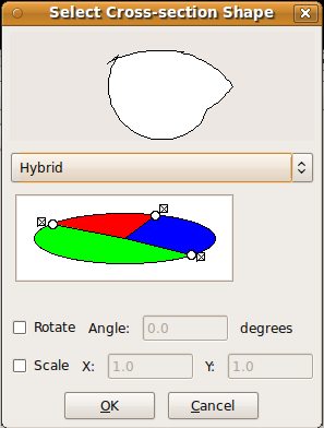
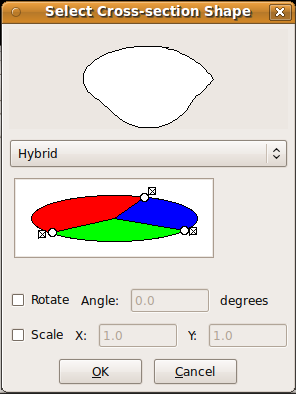
| + | ::The Select Cross-section Shape dialog will be displayed. Click on 2 or more points outside the shape in the lower window to specify the divisions for the shapes to be assigned. | ||
| + | ::Click within each section in turn to specify the shape to be used. The shape for this section of the area is specified using the Select Cross-section Shape dialog as described in the previous sections. | ||
| + | |||
| + | ::The example shows: | ||
| + | :::Red section - ellipse, width = 1.0, height = 0.5 | ||
| + | :::Blue section - lenticular, width = 1.0, height = 0.5, distortion = 0 | ||
| + | :::Green section - ellipse, width = 0.75, height = 0.75 | ||
| + | |||
| + | ::A preview of the resulting shape is displayed in the top window of the dialog. It can be seen that there are discontinuities where the sections meet. These can be smoothed by dragging the circles at the join until a smooth transition is achieved, as shown on the right. | ||
| + | |||
| + | |||
| + | |||
| + | |||
| + | |||
| + | |||
| + | |||
| + | |||
| + | |||
| + | |||
| + | |||
| + | |||
| + | * Rotate - if this is checked then input an angle by which the shape should be rotated. | ||
| + | * Scale - if this is checked then input scale factors for the x and y directions. | ||
| + | |||
| + | ===Repeats=== | ||
| + | |||
| + | # Select Main Menu -> Modeller -> Assign Repeats... or, | ||
| + | # Select Controls -> Modeller -> Repeats | ||
| + | # Select yarn or multiple yarns as described in Edit Yarn/Node Position | ||
| + | # Add/edit values in the Repeats dialog to give repeat vectors. Typically a textile will have two repeat vectors eg x,0,0 and 0,y,0 | ||
| + | |||
| + | |||
| + | ===Properties=== | ||
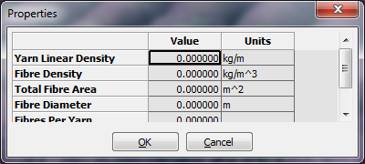
| + | Properties can be set for yarns, either individually or for the whole textile, and matrix. | ||
| + | |||
| + | For all properties both the value and the units can be set in the dialog box. Units are set by entering a string, eg kg/m^3 | ||
| + | |||
| + | [[file:YarnProperties.png|right]] | ||
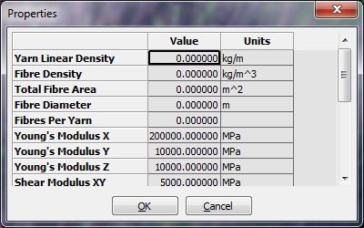
| + | To set yarn properties: | ||
| + | # Select Main Menu -> Modeller -> Assign Yarn Properties... or, | ||
| + | # Select Controls -> Modeller -> Yarn Properties | ||
| + | # In the Properties dialog enter values and units for the whole textile: | ||
| + | ## Yarn Linear Density | ||
| + | ## Fibre Density | ||
| + | ## Total Fibre Area | ||
| + | ## Fibre Diameter | ||
| + | ## Fibres Per Yarn | ||
| + | ## Areal Density, or... | ||
| + | # To set properties for individual yarns select one or more yarns (use Shift+Mouse Click to select multiple yarns) and enter values and units in the Properties dialog: | ||
| + | [[file:TextilePropetiesDialog.png|right]] | ||
| + | ## Yarn Linear Density | ||
| + | ## Fibre Density | ||
| + | ## Total Fibre Area | ||
| + | ## Fibre Diameter | ||
| + | ## Fibres Per Yarn | ||
| + | ## Young's Modulus X | ||
| + | ## Young's Modulus Y | ||
| + | ## Young's Modulus Z | ||
| + | ## Shear Modulus XY | ||
| + | ## Shear Modulus XZ | ||
| + | ## Shear Modulus YZ | ||
| + | ## Poisson's Ratio X | ||
| + | ## Poisson's Ratio Y | ||
| + | ## Poisson's Ratio Z | ||
| + | ## Alpha X | ||
| + | ## Alpha Y | ||
| + | ## Alpha Z | ||
| + | [[file:MatrixProperties.png|right]] | ||
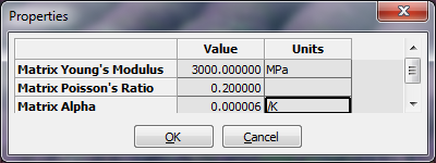
| + | To set the matrix properties: | ||
| + | # Select Main Menu -> Modeller -> Assign Matrix Properties... or, | ||
| + | # Select Controls -> Modeller -> Matrix Properties | ||
| + | # In the Properties dialog enter values and units for the matrix: | ||
| + | ## Matrix Young's Modulus | ||
| + | ## Matrix Poisson's Ratio | ||
| + | ## Matrix Alpha | ||
| + | |||
| + | ==Domain== | ||
| + | |||
| + | The domain is specified so that, after repeats have been specified, the model can be constrained to a specific region. In most cases the domain will correspond to the unit cell of the textile but maintaining a distinction between the two gives added flexibility. | ||
| + | |||
| + | The domain is specified by planes where the space on the negative side of the plane is | ||
| + | considered to be outside of the domain. Each plane is defined as: | ||
| + | Ax + By + Cz + D = 0 | ||
| + | |||
| + | The vector (A, B, C) represents the unit normal to the plane, and D represents the distance | ||
| + | from the plane to the origin. In order to specify an axis aligned bounding box | ||
| + | with minimum of (x1, y1, z1) and maximum of (x2, y2, z2), six planes P need to be defined | ||
| + | as shown in the table below. | ||
| + | |||
| + | {| class="wikitable" style="text-align:center" | ||
| + | |- | ||
| + | ! !! A !! B !! C !! D | ||
| + | |- | ||
| + | ! P0 | ||
| + | | 1 || 0 || 0 || x1 | ||
| + | |- | ||
| + | ! P1 | ||
| + | | -1 || 0 || 0 || -x2 | ||
| + | |- | ||
| + | ! P2 | ||
| + | | 0 || 1 || 0 || y1 | ||
| + | |- | ||
| + | ! P3 | ||
| + | | 0 || -1 || 0 || -y2 | ||
| + | |- | ||
| + | ! P4 | ||
| + | | 0 || 0 || 1 || z1 | ||
| + | |- | ||
| + | ! P5 | ||
| + | | 0 || 0 || -1 || -z2 | ||
| + | |} | ||
| + | |||
| + | The user interface gives two methods of specifying the domain: | ||
| + | # Specify a bounding box with minimum and maximum x, y and z values | ||
| + | # Specify the planes as described above | ||
| + | |||
| + | ===Specify Domain Using Bounding Box=== | ||
| + | |||
| + | # Select Main Menu -> Domain -> Create Box... or, | ||
| + | # Select Controls -> Domain -> Box | ||
| + | # In the Box Domain dialog enter the minimum and maximum x, y and z coordinates | ||
| + | |||
| + | ===Specify Domain Using Planes=== | ||
| + | |||
| + | # Select Main Menu -> Domain -> Create Planes... or, | ||
| + | # Select Controls -> Domain -> Planes | ||
| + | # Enter planes using the Domain Editor dialog: | ||
| + | ## Enter x, y, z and d values for a plane as specified above | ||
| + | ## Select Add Plane | ||
| + | ## Repeat for each plane required | ||
| + | # To edit a plane: | ||
| + | ## Select the plane in the text box | ||
| + | ## Alter the values as required | ||
| + | ## Select Replace Plane | ||
| + | # To delete a plane: | ||
| + | ## Select the plane in the text box | ||
| + | ## Select Delete Plane | ||
| + | |||
| + | ===Edit Domain=== | ||
| + | |||
| + | # Select Main Menu -> Domain -> Edit Domain... or, | ||
| + | # Select Controls -> Domain -> Edit | ||
| + | # The Domain Editor dialog will be displayed and is used as described in the previous section | ||
| + | |||
| + | ===Delete Domain=== | ||
| + | |||
| + | # Select Main Menu -> Domain -> Delete or, | ||
| + | # Select Controls -> Domain -> Delete | ||
| + | |||
| + | Both of these actions will completely delete the domain | ||
| + | |||
| + | ==Rendering== | ||
| + | |||
| + | ===Render Fibre Orientation=== | ||
| + | |||
| + | Renders the fibre orientations on a grid of points. Note that the orientation represented is that of the point at the base of each arrow. Also note that when orientations are output with meshes they are calculated for each element and the orientations represented in this option are for illustrative purposes only. | ||
| + | |||
| + | ===Refresh View=== | ||
| + | |||
| + | Forces the textile to be re-rendered so that any updates (eg made using Python commands) are shown. | ||
| + | |||
| + | ==Tools== | ||
| + | |||
| + | ===Create Pattern Draft=== | ||
| + | |||
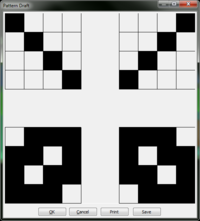
| + | This function will create a pattern draft for textiles created using the 2D and 3D textile weave types. It is not currently implemented for 3D angle interlock textiles. | ||
| + | |||
| + | * Select Main Menu -> Tools -> Select Pattern Draft | ||
| + | ** A dialog will be displayed showing the pattern draft for the current textile as shown below: | ||
| + | [[Image:Pattern4x4.png|400px]] [[Image:2dWeavePatternDraft.png|200px]] | ||
| + | |||
| + | * Select Print to print in the format shown in the dialog | ||
| + | * Select Save to create a text file with a binary version of the pattern as shown below: | ||
| + | |||
| + | 1000 0001 | ||
| + | 0100 0010 | ||
| + | 0010 0100 | ||
| + | 0001 1000 | ||
| + | |||
| + | 0111 1110 | ||
| + | 1101 1011 | ||
| + | 1011 1101 | ||
| + | 1110 0111 | ||
| + | |||
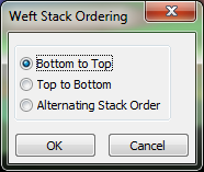
| + | * For 3d textiles the ordering of weft yarn insertion is selected using the dialog below: | ||
| + | [[Image:WeftOrderingDialog.png]] | ||
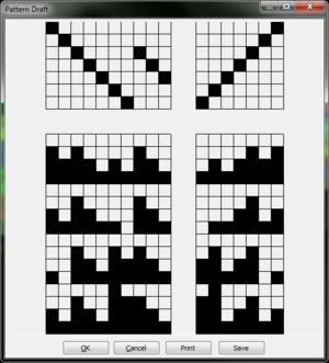
| + | * The pattern draft will then be displayed and may be printed and saved as before. | ||
| + | [[Image:LayerToLayerTextile.png|400px]] [[Image:LayerToLayerPattern.png|300px]] | ||
| + | |||
| + | ===Quick Calculate Domain Volume Fraction=== | ||
| + | |||
| + | * Select Main Menu -> Tools -> Quick Calculate Domain Volume Fraction | ||
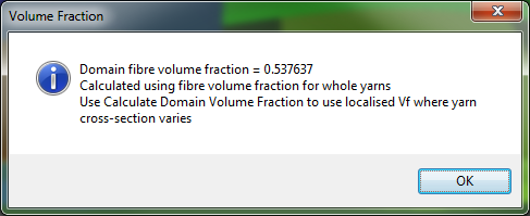
| + | ** The volume fraction will be calculated using the volume fraction for the whole yarn. This may introduce inaccuracies if the domain does not correlate to the size of the yarn and the yarn cross-section changes along its length. The Calculate Domain Volume Fraction gives a more accurate value but is slower. This option is useful where a quick approximation is acceptable. | ||
| + | ** The result is displayed in a dialog as shown: | ||
| + | [[File:QuickVfDialog.png]] | ||
| + | |||
| + | ===Calculate Domain Volume Fraction=== | ||
| + | |||
| + | * Select Main Menu -> Tools -> Calculate Domain Volume Fraction | ||
| + | ** This calculates the volume fraction for the domain based on the localised volume fractions for each element of a volume mesh. | ||
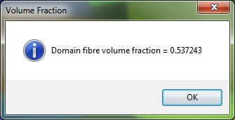
| + | ** The result is displayed in a dialog as shown: | ||
| + | [[File:DomainVfDialog.png]] | ||
| + | |||
| + | ===Yarn Fibre Volume Fraction=== | ||
| − | + | * Select Main Menu -> Tools -> Yarn Fibre Volume Fraction | |
| + | ** Select yarn using the left mouse button. (Shift + left button to select more than one yarn) | ||
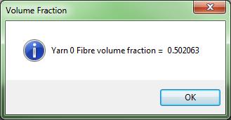
| + | ** The volume fraction for each yarn is displayed in a dialog as shown: | ||
| + | [[File:YarnVfDialog.png]] | ||
| − | + | ===Correct Small Intersections=== | |
| − | + | *Select Main Menu->Tools->Correct Small Intersections | |
| − | + | **Adjusts small interferences in the fibre volume mesh | |
| + | **Takes the individual yarn meshes and corrects intersections based on Textile.DetectInterference() | ||
| + | **Only intended to be used for minor adjustments so will abort if intersections are greater than one volume element in depth | ||
| − | + | ==Options== | |
| − | + | ===Switch Off Messages=== | |
| − | + | Some procedures may be significantly quicker if the messages in the TexGen Output window are switched off. Exporting to a voxel file is one example of this. | |
| − | + | * Select Main Menu -> Options -> Output Messages to switch on/off | |
| + | ** The option will be marked with a tick if messages are switched on | ||
| − | + | ==View== | |
| − | + | ===Zoom=== | |
| − | + | Press and hold right mouse button. Drag in an upwards direction to zoom in, downwards to zoom out. | |
| − | + | ===Pan=== | |
| − | + | Press and hold middle mouse button at point to be moved, then drag to required position. | |
Latest revision as of 15:29, 25 June 2024
Introduction
This user guide gives instructions for using TexGen via the graphical user interface (GUI). A practical introduction to using TexGen with worked examples and exercises can be found in the TexGen chapter in the book Advanced Weaving Technology, DOI https://doi.org/10.1007/978-3-030-91515-5.
Layout
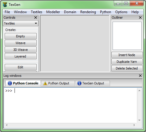
At the centre is a window showing a 3d representation of the textile geometry. Initially when TexGen is loaded this window will be empty, this is because no textile models will have been created yet. After creating a textile model it will become visible, if several textile models are created they will each be open in a separate tab allowing you to work with several models at once.
There are several other windows which can be switched on and off via the drop-down menu at the top in the "Window" section. By default the controls and logs windows will be visible.
The controls window is separated into various sections: Textiles, Modeller, Domain, Rendering and Python. Note that most of these controls are also accessible via the drop-down menu at the top. These controls are used to create textile models, manipulate them and control how they are rendered to the screen amongst other things.
The log windows at the bottom contains an interactive Python Console along with Python Output and TexGen Output windows. The interactive console allows the user to type Python commands and see the results in an interactive manner. This can be useful for small operations and learning how to use the python scripting interface. For inputting a large number of Python commands it is more convenient to save it in a Python script and execute it all at once.
The Python Output log window displays all the Python code executed by the GUI. Essentially every button pressed in the user interface will create a Python command. This is done by design, making it possible to record Python scripts while interacting with the GUI. If you know how to do something with the GUI, you then automatically know how to do it with a Python script because the code is displayed.
The TexGen Output log window displays log and error messages from TexGen. These generally include information on what TexGen is doing, if something goes wrong it is useful to read the log to find out what happened. Error messages will be displayed in red so that they can be easily located.
If new messages are posted one of the log windows while it is inactive, the icon above the window will change. In the case of receiving an error message the icon will change to an error icon.
Finally the outliner window which is hidden by default gives tree representation of the textile model. Which each textile is composed of a several yarns each of which is composed of nodes. This will be covered in more detail in the modelling section.
Textiles Menu
Create Empty Textile
This option creates an empty textile ready to have yarns added using the Modeller options. Either:
- Select Controls -> Textiles -> Empty, or
- Select Main Menu -> Textiles -> Create Empty...
A Textile Name dialog will then be displayed for entering a name for the textile. Leave blank for a default name of Textile, Textile-2 etc.
Create Weave
To use the weave wizard either:
- Select Controls -> Textiles -> Weave, or
- Select Main Menu -> Textiles -> Create Weave...
Create 2D Weave
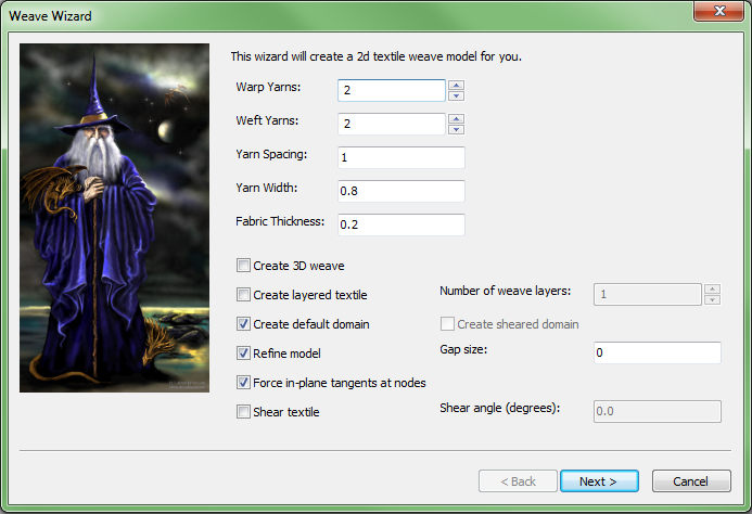
Fill in the textile data on Weave Wizard as follows. Tool tips for each section can be viewed by holding the mouse over the control for about a second.
- Warp Yarns, Weft Yarns - select number of yarns required
- Yarn Spacing - by default this is the same for both warp and weft yarns
- Yarn Width - by default this is the same for both warp and weft yarns
- Fabric Thickness - at this point the yarn height will be taken to be half the fabric thickness (this can be altered in the next dialog if necessary
- Create 3D Weave - leave unchecked for 2D weave
- Create Layered Textile - when checked the Number of Weave Layers control is enabled for selection of the number of layers of the 2D textile.
- Create Default Domain - the default domain is the same as the unit cell, producing a box shaped domain with orthogonal faces.
- Create Sheared Domain - enabled when the Shear textile option is selected. Generates a unit cell domain which lines up with the angle of the sheared yarns in the x-y plane.
- Refine model - if selected this will automatically adjust yarn cross-sections and rotations to create a textile without intersections and with a specified gap between yarns
- Gap Size - Specify the gap between yarns when Refine Model is selected
- Shear textile - if selected this will generate a textile with the weft yarns sheared at the shear angle specified.
- Shear angle - Specify the shear angle in degrees when Shear Textile is selected
Select Next to proceed to Weave Pattern dialog:
This window allows the weave pattern to be set and yarn spacing, width, and height to be adjusted.
- Click on yarn cross-over to switch the vertical order of the crossing yarns and thus define the weave pattern.
- Right click on the top-down view to select a cross-section passing through the selected point. This gives a schematic preview of the cross-section.
- Set yarn spacing, width and height
- Click on boxes running along left and top of window to select one yarn
- Control or Shift and right click to select multiple yarns
- Boxes representing selected yarns now appear in red
- Right click to give pop-up menu. Select required option and enter value in subsequent dialog box
- Changes to width and height will be applied to all selected yarns. Changes to yarn spacing will modifies the spacing between the selected yarn and the yarn after it.
Create 3D Weave
- Create 3D Weave - check this box
- Refine Model/Gap size - these options will now be greyed
- Fill in the rest of the textile data on the Weave Wizard as described for a 2D weave above
Select Next to proceed to Weave Pattern dialog:
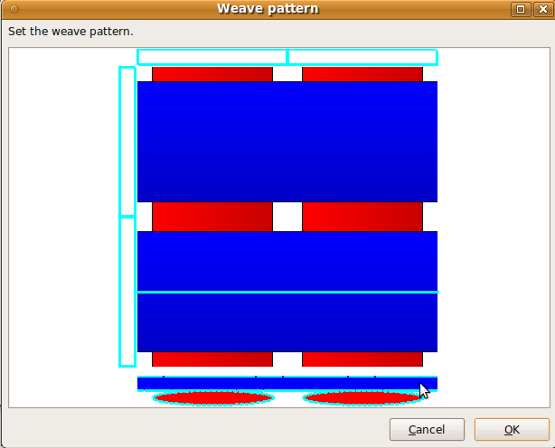
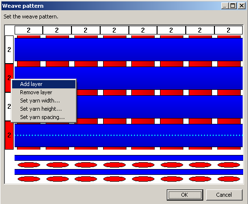
This window allows the weave pattern to be set and yarn spacing, width, and height to be adjusted. Layers of warp and weft yarns can also be added and removed.
- Click on the top-down view to select a cross-section passing through the selected point. This gives a schematic preview of the cross-section.
- The cross-section view is very important when creating 3d weaves because it is the only way to set the vertical order of the warp and weft yarns. Click and drag a cross-over up or down to move it to the desired location. By doing this for each cross-section one after the other the weave pattern can be completely defined.
- Add/remove layers
- Click on boxes running along left and top of window to select one yarn
- Control or Shift and Click to select multiple yarns
- Boxes representing selected yarns now appear in red
- Right click to give pop-up menu.
- Select Add Layers/Remove Layers to add/remove one yarn to each set of yarns chosen
- Set yarn spacing, width and height as for 2D Weave described above
Create 3D Weave
To use the 3D weave wizard either:
- Select Controls -> Textiles -> 3D Weave, or
- Select Main Menu -> Textiles -> Create 3D Weave...
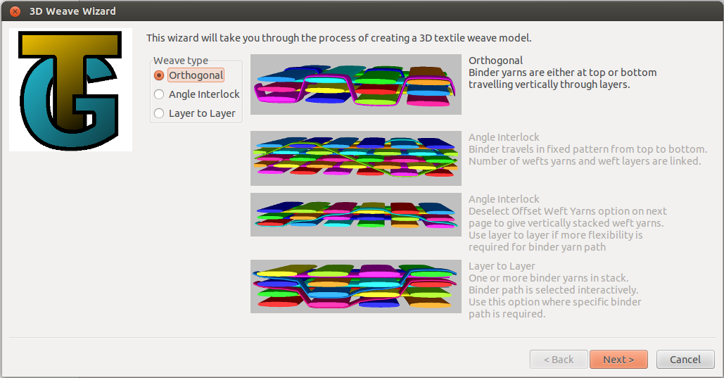
First select the weave type to be created and then select Next to continue to the next page.
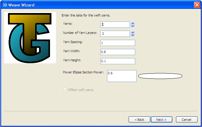
Input the data for the weft yarns on the 3D Weave Wizard as follows. Tool tips for each section can be viewed by holding the mouse over the control for about a second.
- Yarns - select number of yarns required
- Number of Yarn Layers - select the number of weft yarn layers
- Note that for angle interlock weaves the number of yarns and layers are tied so that the correct weave pattern is achieved. Changing one will cause the other to be changed automatically if necessary.
- Yarn Spacing - this is the spacing allowed for the yarn, the yarn being positioned centrally within the space assigned.
- Yarn Width - specify the yarn width
- Yarn Height - specify the yarn height
- Power Ellipse Section Power - specify power. The resulting shape is shown on the dialog
- Offset weft yarns - this is only enabled for the angle interlock weave and results in a weave pattern where rows of weft yarns are offset by half a yarn spacing
Select Next to proceed to warp yarn input dialog. Enter data as for the weft yarns.
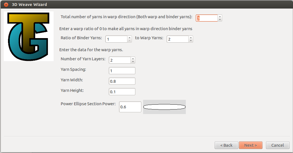
- Total number of yarns in warp direction: This is the total of both straight warp yarns and through thickness binder yarns.
- Ratio of Binder Yarns to Warp Yarns: Specifies the order of binder/warp yarns. If the warp ratio is 0 then all yarns in the warp direction are binder yarns.
- For angle interlock and layer-to-layer weaves the number of layers input is disable and is assigned automatically depending on the number of weft layers.
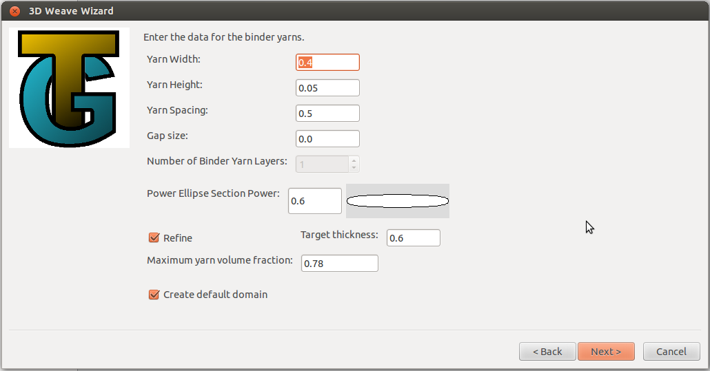
Select Next to proceed to the binder yarn input dialog.
- Yarn Width - specify the yarn width
- Yarn Height - specify the yarn height
- Yarn Spacing - specify the yarn spacing
- Gap size - where possible this forces a gap of the given size between yarns
- Power Ellipse Section Power - specify power. The resulting shape is shown on the dialog
- Number of Binder Yarn Layers - this is only enabled for layer-to-layer weaves
- Refine - this option is only available for orthogonal weaves. Check the box to refine the textile.
- Target thickness - only enabled if refine is selected. Specify the required target thickness for the refined textile. Defaults to the undeformed thickness given by the warp and weft yarn startin heights.
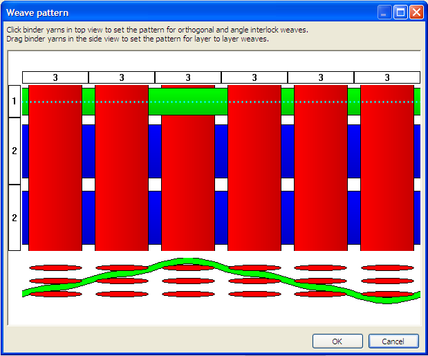
Select Next to proceed to the Weave Pattern dialog or to the Yarn Properties dialogs if the Refine option is selected.
This window allows the weave pattern to be set and yarn spacing, width, and height to be adjusted.
Binder yarns are green, warp yarns blue.
- Orthogonal weave - click on binder yarn crossover point on top view to toggle the binder yarn between top and bottom of the weave.
- Angle interlock - click on binder yarn crossover point on top view to assign top point of binder yarn pattern.
- Layer-to-layer
- Click on binder yarn on top view to select. A schematic preview of the side view for this binder position will be displayed below the top view.
- Drag the binder yarns in the side view to the vertical position required. If there is more than one layer of binder yarns these will all be moved together.
- Set yarn spacing, width and height
- Click on boxes running along left and top of window to select one yarn
- Control or Shift and right click to select multiple yarns
- Boxes representing selected yarns now appear in red
- Right click to give pop-up menu. Select required option and enter value in subsequent dialog box
- Changes will be applied to all selected yarns.
A separate dialog will be displayed for warp, weft and binder yarn properties. When refining the textile the yarn volume fractions are calculated to check that, as the yarns are compressed, the volume fractions stay within realistic limits. If these are exceeded then the refine will stop with an error message stating that the target thickness cannot be achieved.
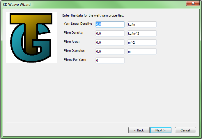
Note that it is not necessary to complete all of these values: either the fibre area, or fibres per yarn and fibre diameter, or yarn linear density and fibre density will be sufficient.
Create Layered
Either:
- Select Controls -> Textiles -> Layered, or
- Select Main Menu -> Textiles -> Create Layered...
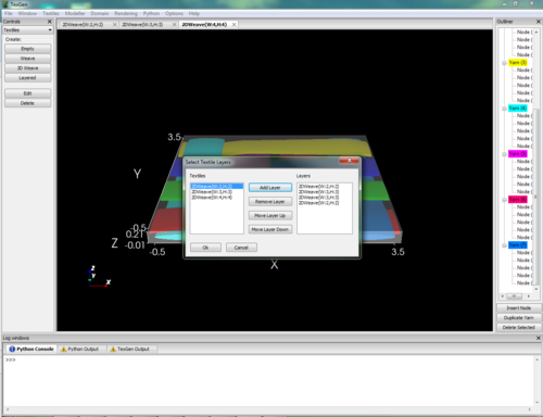
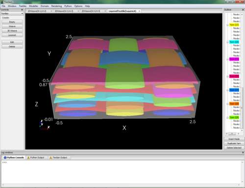
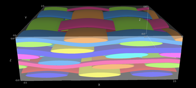
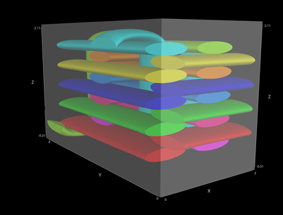
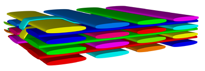
The Select Textile Layers dialog will be displayed. On the left hand side this lists all of the textiles currently loaded in the GUI. These can be selected and then the Add Layer button used to add them to the Layers window on the right hand side. The textiles listed in the Layers window can then be selected and the Remove Layer, Move Layer Up and Move Layer Down buttons used to select the order required. The layered textile will be created with the textiles in the order shown in the dialog as shown below.
Set Layer Offsets
Select Main Menu -> Textiles -> Set Layer Offsets
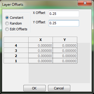
The Layer Offsets dialog will be displayed.
- Constant - enter an x and y offset. This offset will be applied from the bottom of the stack to each layer, relative to the one below.
- Random - random offsets are allocated and are displayed in the table on the dialog.
- Edit Offsets - the table can be edited and the offsets entered.
Nest Layers
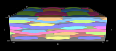
Two nesting options are available, either maintaining the layer offsets already set or moving the layers relative to each other in order to achieve the maximum nesting.
- Maintaining offset
- Select Main Menu -> Textiles -> Nest Layers -> Keep Offsets
- The layers will be moved together, in the z direction, as much as possible without causing intersections. The current x,y offsets between layers is maintained.
- Maximum nesting
- Select Main Menu -> Textiles -> Nest Layers -> Maximum nesting
- The layers will be moved together adjusting the x and y offset between the layers in order to achieve the maximum z movement without causing intersections.
Edit Textile
Either
- Select Textiles -> Edit Textile..
or
- Select Edit from the Textiles menu in the Controls window
If the textile has been created using one of the wizards then it will be reloaded into the appropriate wizard and the pages can then be edited and the textile regenerated.
Note: If the textile has been edited (eg. nodes have been moved) this will not be reflected in the regenerated textile.
Rotate Textile
Either
- Select Textiles -> Rotate Textile
or
- Select Rotate from the Textiles menu in the Controls window
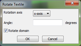
The Rotate Textile dialog will be displayed
- Rotation Axis - select the axis of rotation. For in plane rotation select the z-axis
- Angle - rotation angle in degrees
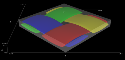
- Rotate Domain - Check to rotate the domain with the yarns. This will result in the section of yarns contained in the domain remaining unchanged (left below). If unchecked the domain will be unchanged and just the yarns rotated (right below).
File Menu
Import
Weave Pattern File
This option generates a TexGen model from a weave pattern file in the format specified below.
- Select File->Import->Weave Pattern File...
- The Open Weave Pattern File dialog is displayed, from which a file for import may be selected.
- Weave Pattern File Format
2D Satin Weave:
1 1 1 1                         First line is layer data, space delimited
1000                            Weave pattern: 1 = warp lifted
0010                                           0 = warp lowered
0100
0001                            No spacing between entries

WEFT_REPEAT                     Use this keyword to generate pattern repeat
WIDTH	6		mm       Yarn data. Row order is unimportant
TOW_AREA	0.2    mm^2      Width, tow area and weft density must all be
WEFT_DENSITY	8	/cm      specified otherwise default values will be used
                         	 to generate the TexGen model
- Additional yarn data. This is optional and will be saved in the yarn properties in the TexGen model
LINEAR_DENSITY	800	tex
FIBRE_DIAMETER	7	um
FIBRE_DENSITY	1.8	g/cm^3
FIBRE_COUNT	12000
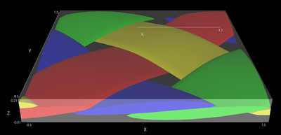
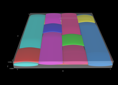
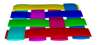
If the tow area is specified with no tow width and height then the TexGen model is generated using the tow area to calculate the width and height of the yarns, assuming a width to height ratio of 6:1 and an elliptical cross-section. Warp and weft spacings are calculated using the width and weft density information. The data above will generate the model shown below:
If the tow area and one of tow width or height are specified then the other dimension (height or width) will be calculated using this data (as in the 3D weave model below). If both tow width and height are specified then these are used, irrespective of the tow area specified.
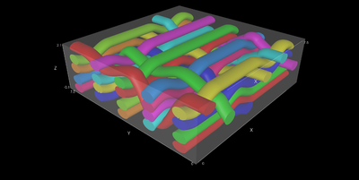
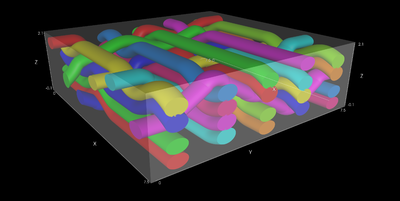
3D Weave: The following file will generate the model shown below:
1 2 3 4 1 2 3 4 1 2 3 4 1 2 3 4 1 2 3 4   Warp layer data, numbered from bottom. Single '1' gives binder yarn
11001111110000001100
00001100111111000000
10001100100011001000
11001000110010001111
11110000100000001000
00001000000011110000
WIDTH	7.5		mm
TOW_AREA  0.2 mm^2
TOW_HEIGHT 	0.4 mm
WEFT_DENSITY	8	/cm
FIBRE_COUNT	6000
LINEAR_DENSITY	800	tex
FIBRE_DIAMETER	6	um
FIBRE_DENSITY	1.8	g/cm^3
WEFT_REPEAT
3D Orthogonal Weave:
1 1 2 3 4 1 1 2 3 4            Warp layer data, numbered from bottom. Single '1' gives binder yarn
1000000000
1100001000
1110001100
1111001110
1111101111
0000010000
0100011000
0110011100
0111011110
0111111111

ORTHOGONAL                     Use orthogonal keyword to automatically stack weft insertions
Export
Surface Mesh
This option creates a surface mesh corresponding to the mesh shown when using the Rendering -> X-Ray option.
VTU and STL File
- Select File->Export->Surface Mesh->STL, VTU File...
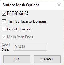
- The Surface Mesh Options dialog will be displayed
- Export Yarns: Select to create a mesh of the yarn surfaces
- Trim Surface to Domain: Select to create yarn meshes conforming to domain bounds
- Export Domain: Select to create a triangulated mesh of the domain surfaces
- Mesh Yarn Ends: Select to create a triangulated mesh across the yarn ends
- Seed size: Used to adjust size of triangulation
- The Save Mesh file menu will be displayed
- Save as type: Use the drop-down menu to select the file type - VTU, STL (ASCII or binary, or SciRun format
ABAQUS File
This option will export the surface mesh of the yarns only
- Select File->Export->Surface Mesh->ABAQUS File...
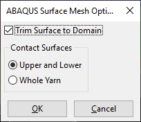
- The ABAQUS Surface Mesh Options dialog will be displayed
- Trim Surface to Domain: Select to output mesh of the yarns bounded by the domain, otherwise the yarns will be output as specified, without repeats
- Contact Surfaces: Outputs element sets for the contact surfaces, either for the upper and lower surfaces separately, or for the whole yarn. Choose Whole Yarn where surfaces are not clearly defined, for example in knitted textiles
Volume Mesh
This option creates a tetrahedral mesh of both the yarns and matrix (ie of the whole domain). Please note that this algorithm does not work well with textiles with vertical or near-vertical yarns.
- Select File->Export->Volume Mesh
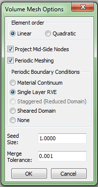
- The Volume Mesh Options dialog will be displayed
- Element Order: Linear creates 4 noded tetrahedra, Quadratic creates 10 noded tetrahedra
- Periodic Meshing: Select to create matching elements on opposite boundaries
- Periodic Boundary Conditions
- Material Continuum: Assumes a material continuum where the RVE is considered to be infinitely small compared to the size of the engineering part.
- Single Layer RVE: Gives a 2.5D simulation, assuming a one layer RVE solving in the x and y directions
- Staggered (Reduced Domain): Applies an offset to the x axis dimension in order to reduce the unit cell size
- X Offset: Enabled when Staggered PBC is selected. Input the proportion of the x axis dimension by which the domain is offset when applying periodic boundary conditions.
- Sheared Domain: Only select if 2D sheared textile has been created. Creates tetrahedra which conform to the sheared domain and creates corresponding periodic boundary conditions.
- None: No boundary conditions are output.
- Periodic boundary condition equations are generated based on the paper "Unit cells for micromechanical analyses of particle-refined composites", Shuguang Li, Anchana Wongsto, Mechanics of Materials 36(2004) 543-572
- Seed size: Controls the mesh density and corresponds to the approximates edge length of the elements. The default value is 1/20th of the domain diagonal length.
- Merge Tolerance:Any gaps between yarns that are smaller than this tolerance will be merged together. This can help to reduce the number of bad quality elements.
After the Volume Mesh Options dialog is accepted the Save Mesh File dialog will be dispayed. The default type for output is an ABAQUS .inp file. This will create the requested boundary conditions and also associated .ele and .ori files containing yarn orientation and volume fraction information. Alternatively a VTK unstructured grid file (.vtu) can be selected which will just output the mesh.
Tetgen Mesh
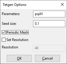
This option allows export of a tetrahedral mesh generated by Tetgen software. The output file is in Abaqus .inp format. Files with the selected name with .poly and .ele formats are also produced.
- The Parameters option allows specification of input switches as described here: http://wias-berlin.de/software/tetgen/switches.html. If the Y parameter is used then the function will generate meshes with matching elements on opposite sides of the domain. Use the o2 parameter to generate second order elements.
- The Seed Size option gives a nominal size for the length of sides of triangles along the domain edge, given as input to the tetgen tetrahedralize function.
- The Periodic check box should be unchecked for non-periodic textiles. In this case the the domain faces will not be triangulated prior to calling the Tetgen tetrahedralization.
- The Set Resolution check box allows the textile resolution to be changed. This sets the resolution for the surface mesh which is used as input for the Tetgen meshing
Information on Tetgen software can be found here: http://wias-berlin.de/software/tetgen/. It should be noted that the mesh generation does not always succeed. Most of the time it exits gracefully with a message that tetrahedralization has failed. Sometimes it will cause TexGen to shut down. It is strongly recommended that the textile is saved before using this option. It has been found that meshes are generated most successfully if a gap is specified in the weave wizards (or if a gap is provided in manually generated textiles).
The .poly file is the input file to the Tetgen tetrahedralize function. A viewer, TetView, can be downloaded here: http://wias-berlin.de/software/tetgen/tetview.html. If the tetrahedralization fails then more information can be gained by downloading the TetGen software and running it from the command line using the .poly file as input. This may show where the program has failed and will enable a bug report to be submitted to the Tetgen project.
Voxel Mesh
Textiles can be exported in voxel mesh format, either as an ABAQUS file including periodic boundary conditions or at a VTU file containing just the nodes and elements.
ABAQUS Voxel File
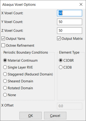
- Select File -> Export -> Voxel Mesh -> ABAQUS Voxel File
- The Abaqus Voxel Options dialog will be displayed
- Select the number of voxels required in x,y and z directions
- Select whether to output yarns, matrix or both
- Select whether to use octree refinement and/or smoothing on the voxel mesh. The Octree Refinement dialog will be displayed when OK is selected.
- Element Type: Select either C3D8R or C3D8
- Periodic Boundary Conditions
- Material Continuum: Assumes a material continuum where the RVE is considered to be infinitely small compared to the size of the engineering part.
- Single Layer RVE: Gives a 2.5D simulation, assuming a one layer RVE solving in the x and y directions
- Staggered (Reduced Domain): Applies an offset to the x axis dimension in order to reduce the unit cell size
- X Offset: Enabled when Staggered PBC is selected. Input the proportion of the x axis dimension by which the domain is offset when applying periodic boundary conditions.
- Sheared Domain: Only select if 2D sheared textile has been created. Creates parallelepiped shaped voxels which conform to the sheared domain and creates corresponding periodic boundary conditions.
- Rotated Domain: Select when a textile has been rotated using the Rotate Textile option with the Rotate Domain option selected. A voxel mesh will be generated which conforms to the rotated domain and creates corresponding periodic boundary conditions.
- None: No boundary conditions are output.
- Periodic boundary condition equations are generated based on the paper "Unit cells for micromechanical analyses of particle-refined composites", Shuguang Li, Anchana Wongsto, Mechanics of Materials 36(2004) 543-572
Octree Refinement
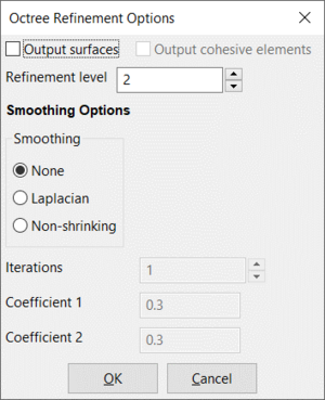
- Output Surfaces - generate sets of nodes for surfaces between yarns and matrix
- Output cohesive elements – define cohesive contact between yarns and matrix
- Only available if surfaces are output. Nodes on the surfaces between yarns and matrix will be duplicated to "decouple" the yarns and matrix. Cohesive contacts will be created
- Refinement level - Each level of refinement reduces the size of element by the factor of 2. Only elements on the interface between two materials or close to it will be refined to this level of refinement.
Smoothing Options
The smoothing algorithm will move the yarn surface nodes according to the Laplacian smoothing algorithm
- Smoothing
- None - no smoothing applied
- Laplacian - Apply Laplacian smoothing to nodes belonging to yarn-matrix surfaces. Each node will be moved by C1*sum(x_i) where x_i are coordinates of neighbouring nodes
- Non-shrinking - Apply two Laplacian smoothings consecutively with coefficients C1 and C1, where C1 < abs(-C2)
- Iterations - number of smoothing iterations
- Coefficient 1 – smoothing coefficient 1
- Coefficient 2 – smoothing coefficient 2
VTU Voxel File
- Select File -> Export -> Voxel Mesh -> VTU Voxel File
- The VTU Voxel Options dialog will be displayed
- Select the number of voxels required in x,y and z directions
- Domain Type
- Box Domain: Default domain created by weave wizards consisting of 6 orthogonal planes
- Sheared Domain: Only select if 2D sheared textile has been created. Creates parallelepiped shaped voxels which conform to the sheared domain
- Rotated Domain: Select when a textile has been rotated using the Rotate Textile option with the Rotate Domain option selected. A voxel mesh will be generated which conforms to the rotated domain
ABAQUS Dry Fibre File
This will create a mesh of just the yarns in the same form as shown by the Rendering->Render Textile Volume option.
- Select File -> Export -> ABAQUS File -> ABAQUS Dry Fibre File..
- The Abaqus Options dialog will be displayed
- X, Y and Z Scale:From the scales entered displacements are calculated and applied to the centre node of each yarn, effectively providing the loading for the Abaqus simulation
- Checking the Compression Plates box will add a pair of plates at the top and bottom surface of the domain.
- Adjust intersections: Small, local adjustments to the volume mesh will be made until the intersections are within the selected intersection tolerance. If the intersection is deeper than one volume mesh element then an error message will be displayed and no correction will take place.
- Regenerate Mesh: This will create a new textile based on the adjusted mesh. The volume mesh is regenerated and used to produce the ABAQUS .inp file. This option will create more evenly spaced elements than if the Adjust Intersections option is used on its own. NB. Ensure that the textile is saved before using this option as it will replace the existing textile.
- Element Type: Select either C3D8R or C3D8
- Contact Surfaces: This option allows contact surfaces to be generated for either the whole yarns or for the upper and lower surfaces. For woven textiles select Upper and Lower. For textiles where there is not a clearly defined upper and lower surface, eg knitted fabric, choose Whole Yarn
Modeller
While the wizards provide an easy way to create textile models, flexibility and control over the geometry is sacrificed. On the other end of the spectrum the modeller allows users total control over textile geometry at the expensive of a slightly steeper learning curve. Note that the modeller can be used to modify models created with the wizards, however if this is done any subsequent changes in the wizard will erase any modifications made.
Create Textile
To invoke the modeller either:
- Select Controls -> Textile -> Empty, or
- Select Main Menu -> Textiles -> Create Empty...
In both cases a dialog box will be given in order to enter a name for the textile, this can be left blank in which case a default name will automatically be assigned.
Add Yarns
To add a single yarn either:
- Select Controls -> Modeller -> Yarn, or
- Select Main Menu -> Modeller -> Create Yarn...
In the Create Yarn dialog:
- Enter start and end coordinates for the yarn
- Enter number of nodes
- The yarn will always initially be created as a straight line with equispaced nodes.
- Once the yarn has been placed it will be visible on screen in wire frame mode.
Edit Yarn/Node Position
Select yarn/node using one of the following methods:
- Click on the yarn/node with the left mouse button
- Hold Shift while selecting yarn/node to select multiple yarns
- Click on the yarn/node in the Outliner tree control
- Hold Shift or Ctrl while clicking on yarns/nodes in outliner tree to select multiple yarns
Nodes are displayed as spheres on the centreline of the yarns.
When either yarn or nodes have been selected they will turn white. X, Y and Z axes will be displayed.
To move yarn/node once it has been selected either:
- Click and drag one of the axes displayed. The yarn/node will be moved in the corresponding direction.
- Precise positioning can be achieved by enabling snapping using Controls -> Modeller -> Snapping
- Edit the coordinates in the Controls -> Modeller -> Position boxes.
Add Nodes
- Select node
- Click Outliner -> Insert Node, or
- Press the Insert key
The new node will be inserted in between the selected node and the previous one. Nodes cannot be inserted before the first node in the yarn.
Duplicate Yarns
- Select yarn
- Click Outliner -> Duplicate Yarn, or
- Press the d on the keyboard
The duplicated yarn will be an exact copy of the yarn at the same location. After duplicating the new yarn should be moved so that they no longer overlap.
Delete Yarns/Nodes
- Select yarn
- Click Outliner -> Delete Selected, or
- Press the Delete key
Set Yarn Path Interpolation
This specifies how the yarn path is interpolated between the nodes.
- Select yarn
- Select Main Menu -> Modeller -> Assign Interpolation... , or
- Select Controls -> Modeller -> Interpolation
- Select interpolation type from drop-down menu
- Periodic - check to give continuity across yarn repeats as follows:
- Linear - continuity of cross-section
- Bezier - continuity of cross-section and tangent(first order continuity)
- Natural Cubic - continuity of cross-section and both first and second order continuity
Set Yarn Cross-Sections
- Select yarn
- Select Main Menu -> Modeller -> Assign Section... , or
- Select Controls -> Modeller -> Section
- Select from the drop-down menu how the cross-section will vary along the length of the yarn
- Constant
- Interpolate Between Nodes - see below
- Interpolate Between Sections - see below
- Select Edit Section to change section shape
Interpolate Between Nodes
- Highlight node to be edited
- Hold Ctrl or Shift key down to select multiple nodes
- Smooth - check this box to give smooth interpolation between section
- Polar - check this box to give polar rather than linear interpolation between sections, useful if there are large rotations between sections
- Select Edit Section to change selected sections
Interpolate Between Sections
- Sections can be specified at specific positions along the length of the yarn
- To add a section:
- Click on Insert Section
- Highlight the section which appears in the text box
- Select the position along the yarn by using the slider or typing into the text box at the bottom of the dialog
- To remove a section:
- Highlight the section to be removed
- Click on Remove Section
- Smooth and Polar - check as required, see Interpolate Between Nodes
- Highlight node to be edited
- Hold Ctrl or Shift key down to select multiple nodes
- Select Edit Section to change selected sections
Specify Cross-sections
After selecting the Edit Section button the Select Cross-section Shape dialog will be displayed.
The shape at the top of the dialog gives a preview of the shape currently specified.
- Select Cross-section from drop-down list and enter parameters as follows:
- Ellipse - Width and height
- Lenticular - This is made up from the intersection of 2 circular sections. Enter width and height. The distortion should be a value between height/2 and -height/2. 0 will give an intersection which is central vertically, height/2 will give a semicircle.
- Power Ellipse - A modified ellipse. Power = 1 gives an ellipse. Power < 1 gives a rectangle with rounded corners (power = 0 gives a rectangle). Power > 1 gives a shape similar to lenticular with rounded ends.
- Rectangle - Width and height. Use of this cross-section rather than a power ellipse with power = 0 will result in a better mesh ( even if other sections along the yarn are power ellipses ).
- Hybrid - This allows a complex section to be created by combining two or more of the above cross-section shapes.
- The Select Cross-section Shape dialog will be displayed. Click on 2 or more points outside the shape in the lower window to specify the divisions for the shapes to be assigned.
- Click within each section in turn to specify the shape to be used. The shape for this section of the area is specified using the Select Cross-section Shape dialog as described in the previous sections.
- The example shows:
- Red section - ellipse, width = 1.0, height = 0.5
- Blue section - lenticular, width = 1.0, height = 0.5, distortion = 0
- Green section - ellipse, width = 0.75, height = 0.75
- The example shows:
- A preview of the resulting shape is displayed in the top window of the dialog. It can be seen that there are discontinuities where the sections meet. These can be smoothed by dragging the circles at the join until a smooth transition is achieved, as shown on the right.
- Rotate - if this is checked then input an angle by which the shape should be rotated.
- Scale - if this is checked then input scale factors for the x and y directions.
Repeats
- Select Main Menu -> Modeller -> Assign Repeats... or,
- Select Controls -> Modeller -> Repeats
- Select yarn or multiple yarns as described in Edit Yarn/Node Position
- Add/edit values in the Repeats dialog to give repeat vectors. Typically a textile will have two repeat vectors eg x,0,0 and 0,y,0
Properties
Properties can be set for yarns, either individually or for the whole textile, and matrix.
For all properties both the value and the units can be set in the dialog box. Units are set by entering a string, eg kg/m^3
To set yarn properties:
- Select Main Menu -> Modeller -> Assign Yarn Properties... or,
- Select Controls -> Modeller -> Yarn Properties
- In the Properties dialog enter values and units for the whole textile:
- Yarn Linear Density
- Fibre Density
- Total Fibre Area
- Fibre Diameter
- Fibres Per Yarn
- Areal Density, or...
- To set properties for individual yarns select one or more yarns (use Shift+Mouse Click to select multiple yarns) and enter values and units in the Properties dialog:
- Yarn Linear Density
- Fibre Density
- Total Fibre Area
- Fibre Diameter
- Fibres Per Yarn
- Young's Modulus X
- Young's Modulus Y
- Young's Modulus Z
- Shear Modulus XY
- Shear Modulus XZ
- Shear Modulus YZ
- Poisson's Ratio X
- Poisson's Ratio Y
- Poisson's Ratio Z
- Alpha X
- Alpha Y
- Alpha Z
To set the matrix properties:
- Select Main Menu -> Modeller -> Assign Matrix Properties... or,
- Select Controls -> Modeller -> Matrix Properties
- In the Properties dialog enter values and units for the matrix:
- Matrix Young's Modulus
- Matrix Poisson's Ratio
- Matrix Alpha
Domain
The domain is specified so that, after repeats have been specified, the model can be constrained to a specific region. In most cases the domain will correspond to the unit cell of the textile but maintaining a distinction between the two gives added flexibility.
The domain is specified by planes where the space on the negative side of the plane is considered to be outside of the domain. Each plane is defined as: Ax + By + Cz + D = 0
The vector (A, B, C) represents the unit normal to the plane, and D represents the distance from the plane to the origin. In order to specify an axis aligned bounding box with minimum of (x1, y1, z1) and maximum of (x2, y2, z2), six planes P need to be defined as shown in the table below.
| A | B | C | D | |
|---|---|---|---|---|
| P0 | 1 | 0 | 0 | x1 |
| P1 | -1 | 0 | 0 | -x2 |
| P2 | 0 | 1 | 0 | y1 |
| P3 | 0 | -1 | 0 | -y2 |
| P4 | 0 | 0 | 1 | z1 |
| P5 | 0 | 0 | -1 | -z2 |
The user interface gives two methods of specifying the domain:
- Specify a bounding box with minimum and maximum x, y and z values
- Specify the planes as described above
Specify Domain Using Bounding Box
- Select Main Menu -> Domain -> Create Box... or,
- Select Controls -> Domain -> Box
- In the Box Domain dialog enter the minimum and maximum x, y and z coordinates
Specify Domain Using Planes
- Select Main Menu -> Domain -> Create Planes... or,
- Select Controls -> Domain -> Planes
- Enter planes using the Domain Editor dialog:
- Enter x, y, z and d values for a plane as specified above
- Select Add Plane
- Repeat for each plane required
- To edit a plane:
- Select the plane in the text box
- Alter the values as required
- Select Replace Plane
- To delete a plane:
- Select the plane in the text box
- Select Delete Plane
Edit Domain
- Select Main Menu -> Domain -> Edit Domain... or,
- Select Controls -> Domain -> Edit
- The Domain Editor dialog will be displayed and is used as described in the previous section
Delete Domain
- Select Main Menu -> Domain -> Delete or,
- Select Controls -> Domain -> Delete
Both of these actions will completely delete the domain
Rendering
Render Fibre Orientation
Renders the fibre orientations on a grid of points. Note that the orientation represented is that of the point at the base of each arrow. Also note that when orientations are output with meshes they are calculated for each element and the orientations represented in this option are for illustrative purposes only.
Refresh View
Forces the textile to be re-rendered so that any updates (eg made using Python commands) are shown.
Tools
Create Pattern Draft
This function will create a pattern draft for textiles created using the 2D and 3D textile weave types. It is not currently implemented for 3D angle interlock textiles.
- Select Main Menu -> Tools -> Select Pattern Draft
- A dialog will be displayed showing the pattern draft for the current textile as shown below:
- Select Print to print in the format shown in the dialog
- Select Save to create a text file with a binary version of the pattern as shown below:
1000	0001
0100	0010
0010	0100
0001	1000

0111	1110
1101	1011
1011	1101
1110	0111
- For 3d textiles the ordering of weft yarn insertion is selected using the dialog below:
- The pattern draft will then be displayed and may be printed and saved as before.
Quick Calculate Domain Volume Fraction
- Select Main Menu -> Tools -> Quick Calculate Domain Volume Fraction
- The volume fraction will be calculated using the volume fraction for the whole yarn. This may introduce inaccuracies if the domain does not correlate to the size of the yarn and the yarn cross-section changes along its length. The Calculate Domain Volume Fraction gives a more accurate value but is slower. This option is useful where a quick approximation is acceptable.
- The result is displayed in a dialog as shown:
Calculate Domain Volume Fraction
- Select Main Menu -> Tools -> Calculate Domain Volume Fraction
- This calculates the volume fraction for the domain based on the localised volume fractions for each element of a volume mesh.
- The result is displayed in a dialog as shown:
Yarn Fibre Volume Fraction
- Select Main Menu -> Tools -> Yarn Fibre Volume Fraction
- Select yarn using the left mouse button. (Shift + left button to select more than one yarn)
- The volume fraction for each yarn is displayed in a dialog as shown:
Correct Small Intersections
- Select Main Menu->Tools->Correct Small Intersections
- Adjusts small interferences in the fibre volume mesh
- Takes the individual yarn meshes and corrects intersections based on Textile.DetectInterference()
- Only intended to be used for minor adjustments so will abort if intersections are greater than one volume element in depth
Options
Switch Off Messages
Some procedures may be significantly quicker if the messages in the TexGen Output window are switched off. Exporting to a voxel file is one example of this.
- Select Main Menu -> Options -> Output Messages to switch on/off
- The option will be marked with a tick if messages are switched on
View
Zoom
Press and hold right mouse button. Drag in an upwards direction to zoom in, downwards to zoom out.
Pan
Press and hold middle mouse button at point to be moved, then drag to required position.
