Extraction of Material Properties using Voxel Meshing and Abaqus
This method creates an Abaqus input file by producing a mesh of regularly shaped hexahedral voxel elements for a textile produced by TexGen. Periodic boundary condition equations are generated based on the paper "Unit cells for micromechanical analyses of particle-refined composites", Shuguang Li, Anchana Wongsto, Mechanics of Materials 36(2004) 543-572. After the Abaqus simulation has been run the material properties are extracted by running a script, provided in the TexGen download, which interrogates the Abaqus .odb file. The procedure is described in the following sections.
Create Textile
- Create a textile either via the GUI or by running a script.
- Assign properties to the matrix and yarns using either
- Modeller -> Assign Matrix Properties... and Modeller -> Assign Yarn Properties... options
or
- From a script using the CTextile SetMatrixYoungsModulus(), SetMatrixPoissonsRatio() and SetMatrixAlpha() functions and the CYarn SetYoungsModulusX(), SetYoungsModulusY(), SetYoungsModulusZ(), SetShearModulusXY(), SetShearModulusXZ(), SetShearModulusYZ(), SetPoissonsRatioX(), SetPoissonsRatioY(), SetPoissonsRatioZ, SetAlphaX(), SetAlphaY() and SetAlphaZ() functions.
- Ensure that the textile has a domain specified. If created using one of the wizards then a default domain will have been assigned. Otherwise create an appropriate domain the size of the textile unit cell as described in the domain user guide
Create Abaqus Voxel File
The Abaqus files for the voxel mesh can be created either in the TexGen GUI or in a script. In both cases the number of voxels in the x,y and z directions must be specified and also the element type, boundary conditions and whether just yarn, matrix or both are being exported. Three files are generated: a .inp file containing the nodes, elements, boundary conditions, load cases and material definitions, a .eld file containing the element data (yarn index, location, volume fraction and distance from surface of yarn) and a .ori file containing the yarn orientation vectors. The yarn data for the elements is calculated at the centre point of each element. The element is assigned to either the appropriate yarn or matrix based on this centre point. It may be necessary to perform a sensitivity study in order to assess the best number of voxels for the particular simulation. Where there are thin yarns, eg binder yarns in a 3D weave, care should be taken to ensure that the voxels are small enough to model the continuous yarn with no gaps.
- ABAQUS Voxel File using the GUI
- Select File -> Export -> ABAQUS File -> ABAQUS Voxel File
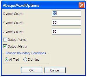
- The Abaqus Voxel Options dialog will be displayed
- Select the number of voxels required in x,y and z directions
- Select whether to output yarns, matrix or both
- Periodic Boundary Conditions
- All Tied: Assumes a material continuum where the RVE is considered to be infinitely small compared to the size of the engineering part.
- Z untied: Gives a 2.5D simulation, assuming a one layer RVE solving in the x and y directions
- ABAQUS Voxel File using a script
